
By Ivan Bailey
The wiring harness in my TR6 is the original. During the restoration, I removed the harness and used a multimeter to test every circuit, repaired any frayed or damaged part of the harness, and rewrapped loose wires where necessary with new harness tape before reinstalling. I did, however, want to improve my headlights and that involved upgrading the lighting circuit. Currently, a 30-year-old switch on the steering column controls power to the headlights. All the power runs the distance from the headlights to the switch – this length creates resistance and a voltage drop at the headlights, reducing the performance of the headlamp. I began researching solutions because of this. Originally, I contacted Advance Autowire, but at that time, only a complete rewiring kit was offered. Further investigation led me to a relay kit that was available from Victoria British, and costing less than $40.00; it is a fully assembled product with straightforward installation instructions. Examining the Victoria British kit further, I found the quality was lacking. Finally, I purchased the Headlight Relay kit, GAC40254, from Moss Motors-Europe that includes 4-Lucas SRB520 relays. By using relays (1), the switch now only controls the on/off to the headlight circuit. In addition, the distance of the wiring to the headlights is reduced, traveling from the relays to the headlights. The hope is that by improving the power available to them the headlights will be brighter.
1 A relay is an electrically controlled switch that uses low power to open or close a high power circuit.
I opened the box and this kit is really a kit… completely unassembled, wires, relays, connectors, blade fuses, and instructions, Figure 1. Feeling a bit intimidated by the seemingly complexity of my purchase I boxed the kit up and put it aside for a later date. Fast forward a few years, Advanced Autowire is now under new ownership, they offer a stand-alone relay kit, and the Moss Kit I bought is still available, but with different components. Not wanting to purchase another kit and not finding any reason not to get started, I pulled the dusty Moss Motors box off the shelf and began my project to upgrade the headlight circuit on the TR6.
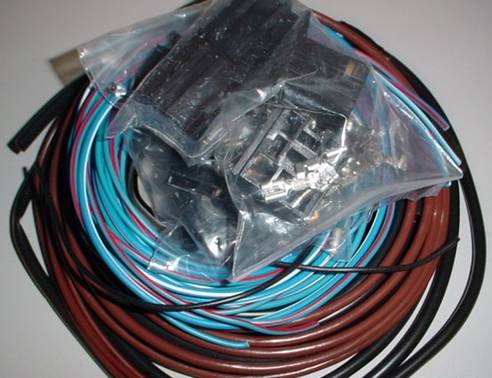
Figure 1. Relay
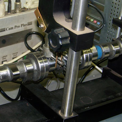
To begin I established the baseline voltage available at the headlights with the current factory wiring. This involved checking the voltage at the battery with the engine running and the headlights turned on, and again at headlights. Using my multimeter set to measure voltage; I connected across the positive and negative battery terminals and obtained a reading of 13.25 volts (DC). I than measured the voltage at the bulb connections and received the following readings from the low and high beams 11.25 and 11.35 respectively. The total voltage drop measured is 2 volts (DC). Slightly greater than 15% and more than the allowed 10% (as stated in the Lucas Fault Diagnosis Manual).
Installation
To start the installation of the Moss Motors Relay Kit, I obtained the necessary tools, including: a Multi-Purpose 6-1 Tool to cleanly cut and strip the wire (and although not essential) a British bullet connector-crimping tool, available from British Wiring, and a high quality soldering gun. The instructions, Figure 2, refer to “lucar” connector terminals; I have always known these as “spade” connectors, so to keep the narrative consistent I will refer to “lucar” connectors throughout this article. The bullet connectors provided in the kit are soldered onto the wires resulting in a solid fit. The solder is flowed into the connector from the top. As I described earlier, the Moss kit is very complete, and the instructions are thorough, however it would have been helpful for Moss to include photographs with the assembly instructions.
Reviewing the contents and instructions it would have been helpful for Moss to include photographs with the assembly instructions.
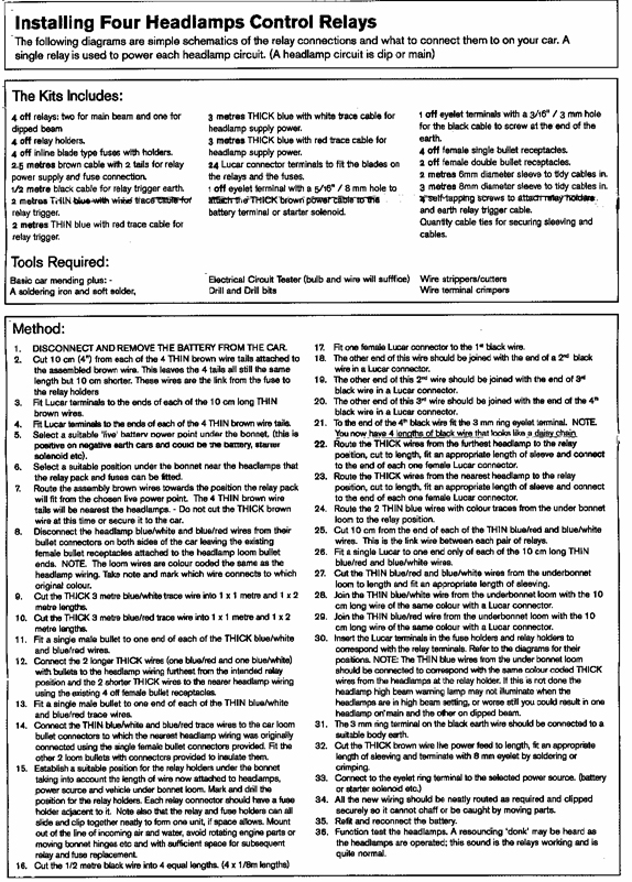
Relay Instructions
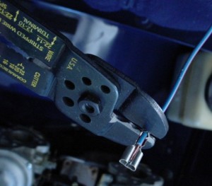
Figure 2
Much of the time installing the kit is spent fitting the appropriate connector to the proper wire. Items 2 through 4 and 16 through 21 and Items 25/26 in the Instructions can be completed at your workbench. It was necessary to convert from meters to feet as the instructions are written for the European community, and although ample lengths of wire are provided in the kit, always remember to measure twice and cut once.
In the photograph Figure 2, you can see that the lucar connector was crimped, using the Multi-Purpose 6-1 Tool, first over the wire plastic and then the stripped copper wire before soldering.
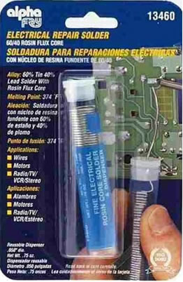
Figure 3 Solder
After the connections were crimped, they were then soldered using rosin-cored solder. This solder can be bought at a local electronics or hardware store, Figure 3.
Be sure you have a powerful enough soldering gun so the heat is only applied to the connections being soldered for a few seconds, wicking the molten solder into the connection. Figure 4 A Multi-Purpose 6-1 Tool will find many uses in your toolbox.
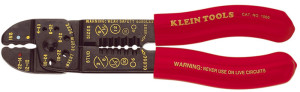
Figure 4. Multi-purpose 6-1 Tool
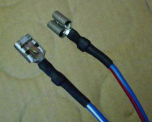
Figure 5
A recommendation is to use several layers of heat shrink tubing to aid the support and protection of the wire at the soldered end. Note, any additional layers of heat shrink tubing on the wires that snap into the relay holders would make them too massive to fit, Figure 5 .
The relay holders lock together with the fuse holders, Item 15 of the Instructions and begin to take shape, Figure 6.
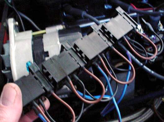
Figure 6
The soldered wires snap into place within the relay holders. Each wire must be properly located into the relay holder to conform to the design of the electrical relay. Using the Moss Motors provided schematic , see Figure 8, 86 is the relay switching (control) circuit input, 85 is the relay switching (control) circuit output, 30 is the power circuit input, 87 is the power circuit output.
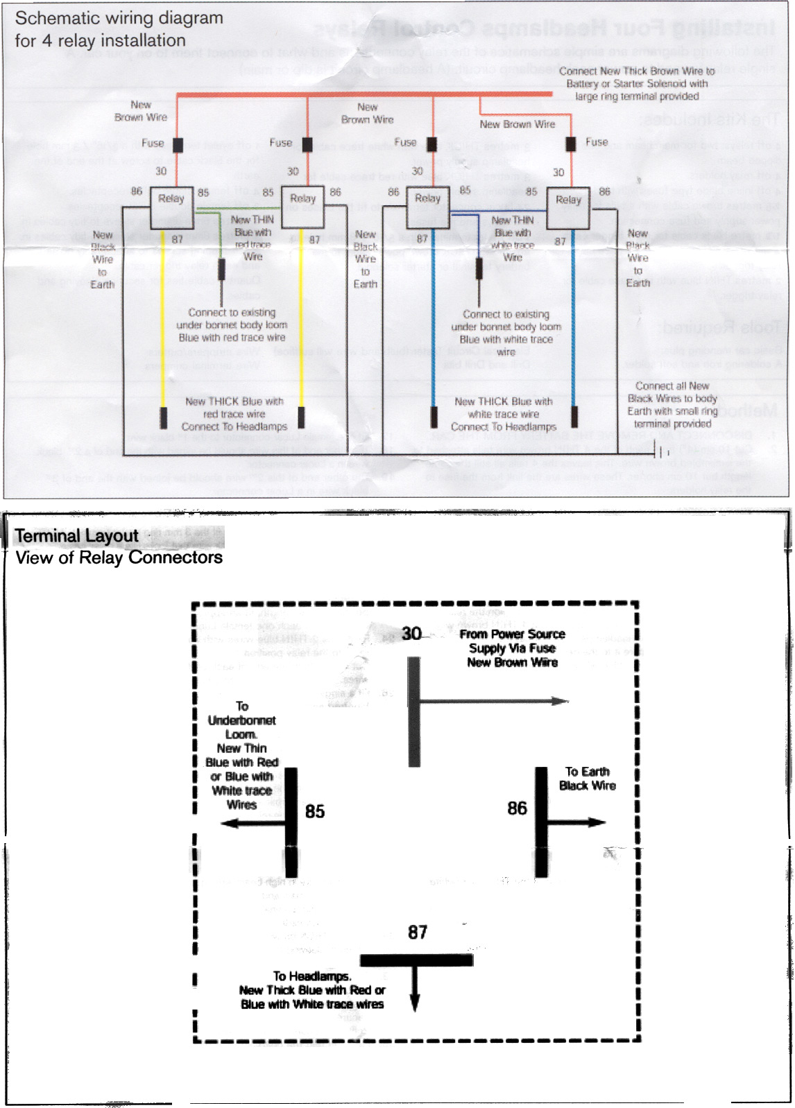
Figure 8
Once the fabrication and assembly of the components was complete, it was time to move to the car, remove the battery, remove the two stay rods, the radiator shroud, and the overflow bottle; this allowed me to better locate and identify the original wires in the harness. The best part of this kit is that the original harness is not cut or modified; rather a new circuit is installed into the current harness. The instructions have you locating a suitable position for the assembled relays, Item 15 in the instructions, and drilling and mounting them. I used double sided-tape to position the assembled relays during the routing of the wires in the engine bay. Once I was comfortable with the location and positioning, I permanently mounted the relays using machine screws and nyloc nuts instead of the metal screws provided in the kit.
To improve the fit of the relay against the engine bay compartment, I used a piece of heavy black rubber cut to size as a shim, Figure 9. These rubber pieces were installed behind the relay holder and shaped to fit the contour of the inner front wheel.
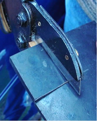
Figure 9
A picture of the mounted relay assembly showing the rubber shims is at Figure 10.
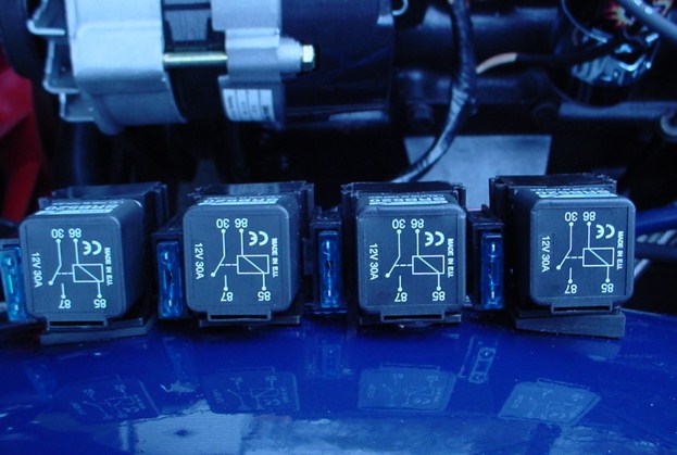
Figure 10
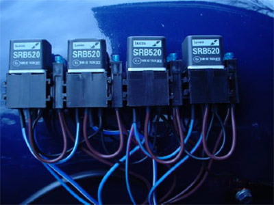
Figure 11 Installed Relay
Plastic sleeving is included in the kit is to cover the new wires after you cut them to length. I had to pull the wires through the sleeves because if you try to feed them by pushing through the sleeve, eventually friction will prevent their passage beyond a few feet. To do this I used a length of thin solid copper wire and ran that through the sleeving first, then taped the wires that go through the sleeve to this sturdy copper wire and pulled them through.
The “Black” ground wire from the relay assembly was attached to the bolt that secures the driver side stay rod, eliminating the need to drill an additional hole into the bodywork, Figure 12. See Item 31 in the Instructions.
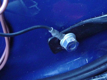
Figure 12
The heavy “Brown” live feed wire was routed along the driver’s side of the engine bay, following the original harness. It was then tucked behind the wiper motor, behind the top of the battery, then down to my selected power source I secured this wire against the firewall using plastic clips.
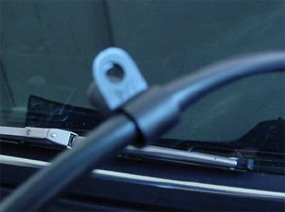
Figure 13 Plastic clip
The clips where then a pop-riveted to the firewall resulting in a clean look and a properly secured wire.
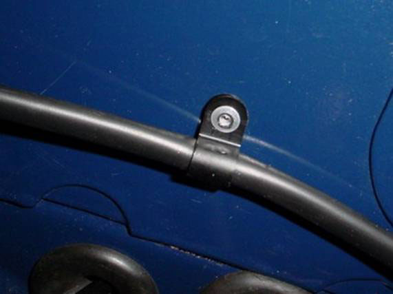
Figure 14 Secured to firewall with pop-rivets
Evaluation and Conclusion
With the new relays and upgraded wiring installed, it was now time to replace the sealed beam headlights with new Cibie 7” brand replaceable bulb headlamp units from Daniel Stearn Lighting.
Daniel Stern has the reputation as the go to guy for automobile lighting needs. When it was time to begin this project I asked Daniel to recommend a set of headlights for the TR6 and tell me why they are the best. He replied the Cibie lights provide a wider beam pattern than some of the other brands and directed me to website Danielsternlighting.com to view some comparison tests. He also cautioned me to be careful of “reproduction” Lucas headlights, all made in China or India with zero optical engineering: “One might as well take a plaster cast of a pair of contact lenses and try to make another set of lens from it”. He claims that none of these lamps provide even minimally adequate light for any kind of normal roadway speeds. Following his advice and given the rather low capacity of my new, but original factory equipped Lucas 16 ACR Alternator; I selected the 60/55w high output bulbs.
Installation of the new headlights was a simple as changing out the original sealed beam headlights. Remove the chrome trim ring, Figure 15, unscrew the three screws that secure the retaining rim and bulb, Figure 16, drop the bulb down, and pull the connector off the headlight. Assembly is the reverse with the only extra step being to install the halogen bulb into the new glass headlight and push on the included rubber gasket, Figure 17, which goes on behind the halogen bulb to seal out water and dust.
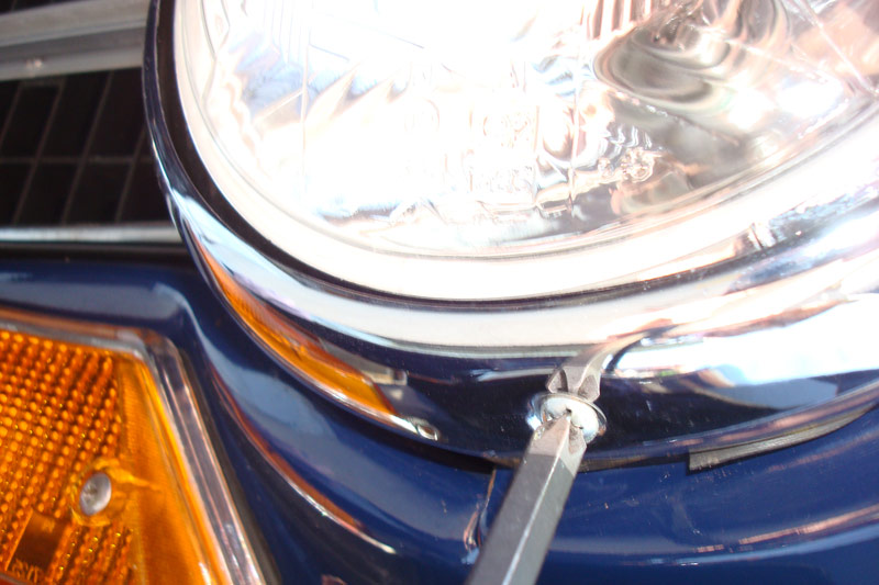
Figure 15 Removing chrome trim
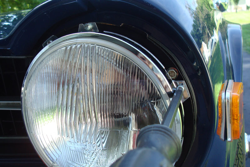
Figure 16 Removing headlight
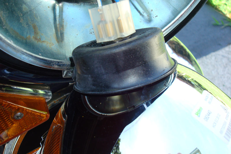
Figure 17 Replacing bulb
Finally, I retested the lighting circuits’ voltage and obtained these new figures: with the headlights on and the engine idling I again measured a reading of 13.25 volts (DC) at the battery and at the bulb connections from the low and high beams 12.77 and 12.71 (2) respectively. The new wiring improved the available power to the headlights by 1 volt (DC). In addition, the total voltage lost is less than one-half a volt, well within the allowed 10%.
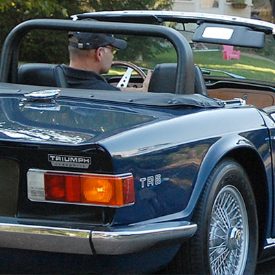
The headlights were simple and straightforward to install…they look great and provide an excellent improvement over the factory stock sealed headlights. With the upgraded wiring harness fitted and the new lights adjusted and secured…let’s SEE where we can go!